
1. Entwodiksyon
The Sealey Digital Automotive Analyser Model TA201 is a compact, multi-function diagnostic tool designed for automotive applications. It features a four-digit, 22mm high-contrast LCD display with a backlight for clear readings in various conditions. This analyser is equipped with auto-ranging, data-hold, and auto-power-off functions to enhance usability and battery life. A key feature is the included inductive coupler, which allows for quick and efficient engine RPM measurements.
This manual provides detailed instructions to help you understand and effectively use all functions of your TA201 analyser, ensuring accurate and reliable automotive diagnostics.

Figure 1: The Sealey Digital Automotive Analyser Model TA201, showing the main unit, inductive coupler, and thermocouple probe.
2. Pake kontni
Before proceeding, please verify that all components are present in your package:
- Sealey Digital Automotive Analyser (Model TA201)
- Inductive Coupler (IC)
- Test Probe Leads (Red and Black)
- Crocodile Clip Leads (Red and Black)
- Thermocouple Lead
- Manyèl Itilizatè (dokiman sa a)

Figure 2: All included accessories: test leads, crocodile clips, inductive coupler, and thermocouple.
3. Enstalasyon ak Premye Operasyon
3.1. Powering On / Off
To power on the analyser, rotate the central function dial from the "OFF" position to any desired measurement function. The LCD display will illuminate. The unit features an auto-power-off function to conserve battery life after a period of inactivity.
3.2. Konekte fil tès yo
Always ensure the analyser is off before connecting or disconnecting test leads. Insert the red test lead into the "VΩmA" input jack and the black test lead into the "COM" input jack for most voltage, resistance, and current measurements. For high current measurements (up to 10A), insert the red lead into the "10A" input jack.
3.3. Montre ak Kontwòl
- Ekspozisyon LCD: Montre lekti mezi, inite, ak endikatè fonksyon.
- Bouton ekleraj: Aktive ekleraj dèyè ekran an pou pi bon vizibilite nan kondisyon ki pa klere anpil.
- Bouton MODE: Toggles between different measurement modes within a single function (e.g., AC/DC voltage, frequency/duty cycle).
- Bouton RANGE: Manually selects the measurement range. The analyser typically operates in auto-ranging mode by default.
- Bouton REL: Aktive mòd mezi relatif la, pou montre diferans ki genyen ant lekti aktyèl la ak yon valè referans ki estoke.
- Bouton HOLD: Li bloke lekti aktyèl la sou ekran an. Peze ankò pou lage li.
4. Operating Instructions: Measurement Functions
The Sealey TA201 offers various functions for comprehensive automotive diagnostics. Select the desired function by rotating the central dial.
4.1. Engine RPM Measurement (Tachometer)
This function measures engine revolutions per minute (RPM) using the inductive coupler.
- Connect the inductive coupler to the analyser.
- Rotate the dial to the "RPM" position.
- Clip the inductive coupler around the spark plug lead of the cylinder you wish to measure. Ensure a secure connection.
- The display will show the engine RPM. Use the "DIS" button to select between 4-stroke and 2-stroke engine types, and "x1" or "x10" for different RPM ranges as needed.
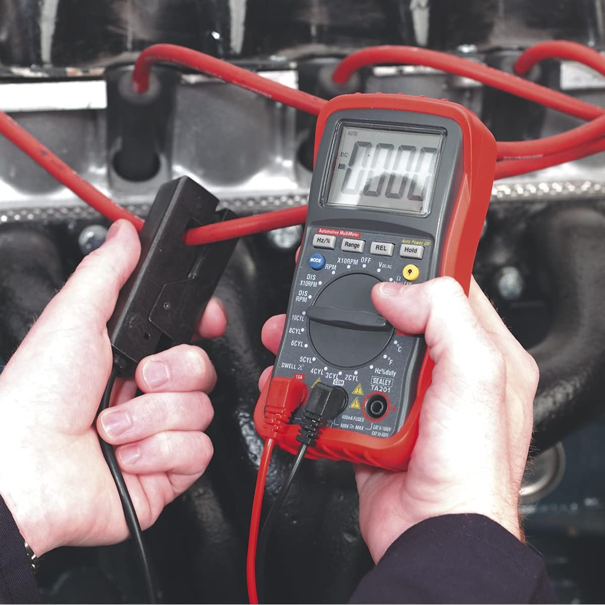
Figure 3: Measuring engine RPM using the inductive coupler clipped onto a spark plug lead.
4.2. Dwell Angle Measurement
Measures the dwell angle for various cylinder configurations.
- Connect the test leads appropriately (refer to vehicle service manual for specific connection points, typically to the distributor or ignition coil negative terminal).
- Rotate the dial to the "DWELL" position.
- Use the cylinder selection buttons (2Cyl, 3Cyl, 4Cyl, 5Cyl, 6Cyl, 8Cyl, 10Cyl) to match your engine's configuration.
- The display will show the dwell angle in degrees.
4.3. DC Voltage Measurement (VDC)
Mezire vòl kouran dirèktage, suitable for battery and charging system checks.
- Connect the red test lead to the positive (+) point and the black test lead to the negative (-) point of the circuit.
- Rotate the dial to the "V-" position. The analyser will auto-range.
- Ekspozisyon an pral montre DC voltage.

Figure 4: Measuring the voltage of a car battery using the test leads.
4.4. AC Voltage Measurement (VAC)
Mezire vòl kouran altènatiftage.
- Konekte fil tès yo atravè vòltaj AC a.tage sous.
- Rotate the dial to the "V~" position. The analyser will auto-range.
- Ekspozisyon an pral montre AC voltage.
4.5. DC Current Measurement (ADC)
Measures direct current flow.
- Enpòtan: To measure current, the analyser must be connected in series with the circuit. Ensure the circuit is de-energized before connecting.
- For measurements up to 400mA, connect the red lead to "VΩmA" and the black lead to "COM". For measurements up to 10A, connect the red lead to "10A" and the black lead to "COM".
- Rotate the dial to the "A-" position.
- Apply power to the circuit. The display will show the DC current.
4.6. AC Current Measurement (AAC)
Measures alternating current flow.
- Enpòtan: Connect the analyser in series with the circuit. Ensure the circuit is de-energized before connecting.
- For measurements up to 400mA, connect the red lead to "VΩmA" and the black lead to "COM". For measurements up to 10A, connect the red lead to "10A" and the black lead to "COM".
- Rotate the dial to the "A~" position.
- Apply power to the circuit. The display will show the AC current.
4.7. Resistance, Continuity, and Diode Test (Ω)
This position on the dial allows for measuring resistance, checking circuit continuity, and testing diodes. Ensure the circuit or component is de-energized before performing these tests.
4.7.1. Mezi rezistans
- Connect the test leads across the component or circuit to be measured.
- Rotate the dial to the "Ω" position. The analyser will auto-range.
- The display will show the resistance in Ohms (Ω), kilo-Ohms (kΩ), or Mega-Ohms (MΩ).
4.7.2. Tès kontinwite
- Rotate the dial to the "Ω" position and press the "MODE" button until the continuity symbol (a speaker icon) appears.
- Touch the test leads across the component or circuit. A continuous beep indicates continuity (low resistance).
4.7.3. Dyòd tès
- Asire w ke dyòd la dekonekte nan sikwi a.
- Rotate the dial to the "Ω" position and press the "MODE" button until the diode symbol appears.
- Connect the red lead to the anode and the black lead to the cathode. A forward voltage gout ap parèt.
- Reverse the leads. The display should show "OL" (Open Loop) for a good diode.
4.8. Frequency and Duty Cycle Measurement (Hz/%)
This position on the dial allows for measuring the frequency and duty cycle of pulse waveforms.
4.8.1. Mezi Frekans (Hz)
- Connect the test leads across the signal source.
- Rotate the dial to the "Hz/%" position. The display will show the frequency in Hertz (Hz).
4.8.2. Duty Cycle Measurement (%)
- Connect the test leads across the signal source.
- Rotate the dial to the "Hz/%" position and press the "MODE" button to switch to duty cycle measurement.
- The display will show the duty cycle as a percentage.
4.9. Mezi Tanperati (°C/°F)
Measures temperature using the supplied thermocouple.
- Connect the thermocouple lead to the designated input jacks (refer to the analyser's input ports, typically marked for temperature).
- Rotate the dial to the "°C/°F" position.
- Mete pwent tèmokoupl la nan pwen kote ou vle mezire tanperati a.
- Use the "MODE" button to toggle between Celsius (°C) and Fahrenheit (°F).
5. Antretyen
5.1. Netwayaj
Wipe the analyser with a dry, soft cloth. Do not use abrasive cleaners or solvents. Ensure no moisture enters the casing.
5.2. Ranplasman batri
When the low battery indicator appears on the display, replace the batteries immediately to ensure accurate readings. Refer to the battery compartment cover for instructions on accessing and replacing the batteries (typically 9V battery).
5.3. Depo
Store the analyser in a cool, dry place, away from direct sunlight and extreme temperatures. If storing for extended periods, remove the batteries to prevent leakage.
NAN. Depanaj
- Pa gen ekran/Inite a pa limen:
- Check if the function dial is set to an "ON" position.
- Verify battery installation and charge level. Replace batteries if necessary.
- Erratic RPM Readings:
- Ensure the inductive coupler is securely clipped around the spark plug lead.
- Try repositioning the inductive coupler closer to the spark plug.
- Verify the correct engine type (2-stroke/4-stroke) and RPM range (x1/x10) are selected using the "DIS" button.
- Some spark plug leads or caps may interfere with inductive pickup. Experiment with different leads if possible.
- "OL" (Overload) or "OPEN" Display:
- The measured value exceeds the selected range. If in manual range mode, select a higher range. If in auto-ranging, this indicates an open circuit or a value beyond the analyser's maximum capability.
- For continuity/diode tests, "OL" indicates an open circuit or a reverse-biased diode.
- Lekti ki pa kòrèk:
- Check battery level. Low batteries can affect accuracy.
- Asire w ke fil tès yo byen konekte epi yo pa domaje.
- Verify the correct function and range are selected for the measurement.
- Ensure the component or circuit is isolated if required (e.g., for resistance, diode, capacitance).
7. Espesifikasyon
The following table details the technical specifications of the Sealey Digital Automotive Analyser Model TA201:
| Karakteristik | Spesifikasyon |
|---|---|
| Nimewo Modèl | TA201 |
| Ekspozisyon | 4-digit, 22mm High Contrast LCD with Backlight |
| Tachometer (RPM) - 4-Stroke | 600-4000 (x1)rpm, 600-12000 (x10)rpm |
| Tachometer (RPM) - 2-Stroke | 300-4000 (x1)rpm, 300-6000 (x10)rpm |
| Dwell Angle - 2Cyl | 0-180° |
| Dwell Angle - 3Cyl | 0-120° |
| Dwell Angle - 4Cyl | 0-90° |
| Dwell Angle - 5Cyl | 0-72° |
| Dwell Angle - 6Cyl | 0-60° |
| Dwell Angle - 8Cyl | 0-45° |
| Dwell Angle - 10Cyl | 0-36° |
| AC Voltage | 400mV, 4V, 40V, 400V, 600V (Auto-Ranging, except 400mV) |
| DC Voltage | 400mV, 4V, 40V, 400V, 600V (Auto-Ranging) |
| AC aktyèl | 400µA, 4000µA, 40mA, 400mA, 4A, 10A (Auto-Ranging for µA & mA) |
| DC aktyèl | 400µA, 4000µA, 40mA, 400mA, 4A, 10A |
| Pwa atik | 1.41 liv (0.64 kg) |
| Dimansyon pwodwi (L x W x H) | 3.07 x 5.2 x 6.93 pous |
| Manifakti | Lanmè |
8. Garanti ak sipò
For information regarding the product warranty, please refer to the documentation provided with your purchase or contact Sealey customer support directly. Warranty terms and conditions may vary based on region and retailer.
For technical assistance or further inquiries, please visit the official Sealey websit la oubyen kontakte sant sèvis otorize yo.